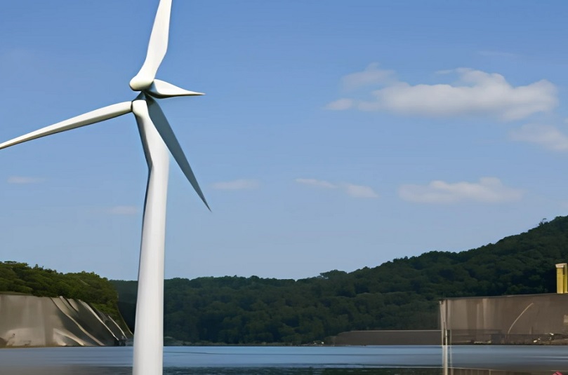
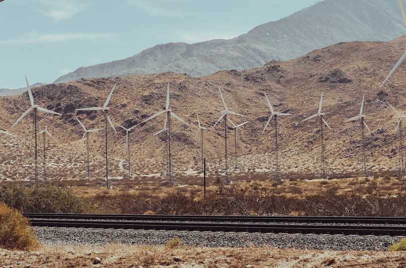
Commercially, wind turbines are currently classified into four types, with additional types expected in the future. Each type has its own standard features and operating conditions that have been agreed upon by the industry. They are classified as Types 1 through 4.
Type 1
Type 1 wind turbine design is the oldest and the simplest to build. The system consists of a squirrel cage induction generator directly connected to the grid without power conversion. The system has a gearbox that converts the slow speed motion of the blades to fast speed, higher than the synchronous speed of the generator, to produce electricity. The system may have pitch control. The turbines at the site are connected to a bus known as a farm connection point. Since the output voltage of most turbines is relatively low, 120–690 V, a step-up transformer is used to increase the voltage of generated power to the voltage of the grid side. The transformer is known as a generation step-up transformer (GSU Xfm) A large number of wind farms are located far from the utility grid. Hence, a transmission line connecting the farm to the grid is needed. This line is often called the trunk line.

Type 2
Type 2 wind turbine consists of a slip-ring (wound rotor) induction machine. The rotor of the machine is accessible and resistance is connected to the rotor windings through a converter. The converter regulates the amount of power consumed by the resistance. This system is considered a variable slip type because the resistance changes the slip of the generator. Thus, the turbine operates at slightly variable speeds allowing the turbine to handle a wider range of wind speeds as compared with Type 1. Also, the amount of power consumed by the resistance provides some form of regulated output power feeding the grid. If less power is needed by the grid, more power is consumed in the resistance. This is similar in function to the dynamic braking of electric motors.

Type 3
Type 3 wind turbine is the most common design today. It is known as a doubly fed induction generator (DFIG). The system consists of a wound rotor induction generator with two converters injecting an adjustable voltage into the rotor circuit at an adjustable frequency and phase shift. Both converters operate in the forward or reversed mode (ac/dc or dc/ac). The converter that is connected to the rotor circuit is called the rotor converter. The one connected to the grid is called a line converter. Depending on the needed action, the power flow through the converters could be from the grid to the rotor or the other way. The converter is sized to allow as much as 1/3 of the rated power of the turbine to pass through it.
With the DFIG, the wind turbine can have a flexible operation and a good level of control. Among the advantages of the DFIG are as follows:
- It can generate electricity when the speed of the wind is low causing the generator to spin below its synchronous speed. This way, the generating range of the turbine is much wider than that for type 1 or 2.
- The turbine can regulate its output power and voltage.
- The system can support and stabilize the grid.
The aforementioned features of the DFIG make the system similar to conventional power plants in terms of control and operation. This is one of the main reasons for the popularity of the DFIG.

Type 4
In the Type 4 wind turbine system, the gearbox is removed. This is a major benefit as the gearbox is one of the most expensive components of the system and also fails more frequently than other key parts. The generator used in this type is often a synchronous generator with either an electric or permanent magnet. In some type 4 systems, the generator can be an induction machine. In either case, the generator has a large number of poles to reduce its synchronous speed. This is important since we eliminated the gearbox. Thus, the diameter of the generator is larger than that of the other types making the nacelle wider in diameter. Since wind speed is variable, the frequency of the power output is also variable.
This variable frequency generator cannot be connected to the fixed frequency grid. To solve this problem, a converter is installed between the generator and the grid. The function of the converter is to receive the variable frequency power of the generator and convert it to the fixed frequency needed by the grid. The converter of the Type 4 system is designed to handle the full power of the turbine. Thus, it is called a full converter.